
ENMG / LOAD TRANSIENT SUPPRESSORS
DM-L
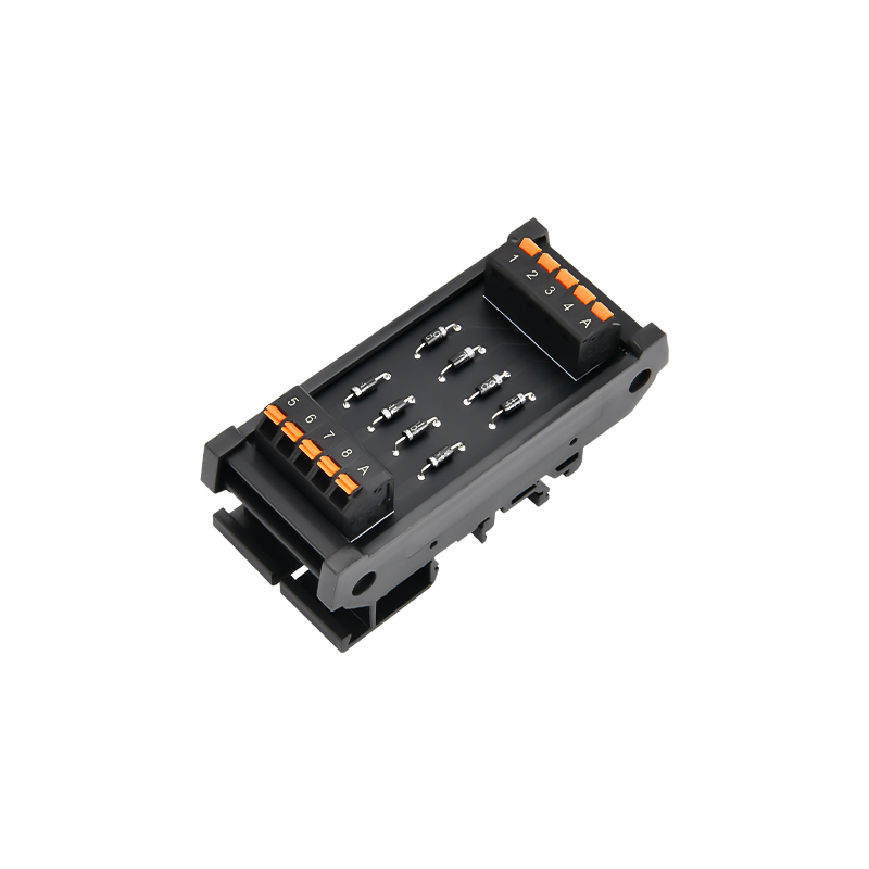
Multi-channel diode suppression modules
DIN-rail diode terminals for application-specific DC inductive-load suppression, with screw or spring connections and selectable common arrangements.
Request a quote ↗TECHNICAL DATA / DM-L
Specifications & selection.
- 8, 16 and 32-channel standard configurations.
- 1N4007 diode versions; other suppression components by specification.
- Common-anode, common-cathode or individually isolated diode paths available.
| Channels | Screw | Spring | L × W × H (mm) |
|---|---|---|---|
| 8 | DM-LS 1N4007×8/COM A or /COM K | DM-LM 1N4007×8/COM A or /COM K | 38 × 87 × 39 |
| 16 | DM-LS 1N4007×16/COM A or /COM K | DM-LM 1N4007×16/COM A or /COM K | 59 × 87 × 39 |
| 32 | DM-LS 1N4007×32/COM A or /COM K | DM-LM 1N4007×32/COM A or /COM K | 100 × 87 × 39 |
| Parameter | Value |
|---|---|
| Package | DO-41 |
| Repetitive reverse peak voltage | 1000 V |
| Average forward current | 1 A per diode; thermal conditions must be verified |
| Non-repetitive forward surge | 30 A, 8.3 ms single half-sine |
| Forward drop | 1.0 V at 1 A in source; verify supplied diode datasheet |
| Reverse leakage | 5 μA at 25 °C / 50 μA at 100 °C junction |
| Junction range | −55 to +175 °C; not module ambient |
| Parameter | Value |
|---|---|
| Operating / storage ambient | −20 to +50 °C / −40 to +70 °C |
| Strip length | 8 mm |
| Rigid / flexible conductor | 0.2–4 / 0.2–2.5 mm² |
| AWG range in source | 24–12 AWG; select the exact terminal specification |
| Mounting | 35 mm DIN rail |
| Dimension tolerance / mass | ±0.5 mm / not specified |
Selection & installation notes
- The source calls COM A common anode and COM K common cathode, but its positive/negative supply instructions are contradictory for flyback operation. Do not wire from those labels alone; obtain the exact schematic and verify diode orientation.
- A flyback diode must be reverse-biased during normal DC energization. Incorrect polarity can short the supply. Verify the complete circuit with power isolated before use.
- 1000 V and 1 A are diode component figures, not verified module working voltage or simultaneous channel ratings. Confirm terminal insulation, PCB spacing, common-path current and thermal limits.
- Suppression may delay inductive-load release. Confirm the required release time and energy handling; the standard diode version is not an AC suppression module.
- Custom TVS, Zener, Schottky, fast diode, MOV, GDT and RC versions require their own ratings and wiring. Do not transfer the 1N4007 specification to them.
Based on the official Chinese product page and selection charts ↗. Checked 2026-09-15. Confirm the current specification for the exact model when ordering.
TECHNICAL RESOURCES
Plan your integration.
ENMG wiring terminals — English product-family brochure.
This is a product-family brochure. Request a model-specific datasheet and installation drawing with your inquiry.