
ENMG / PALM & FOOT SWITCHES
EFAK
Palm and foot switch series
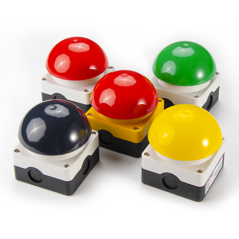
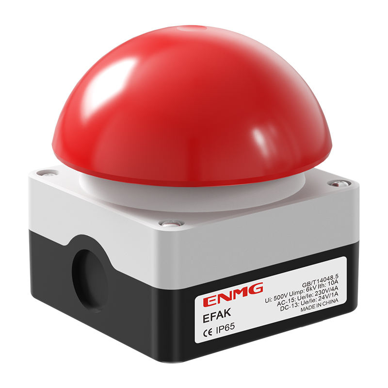
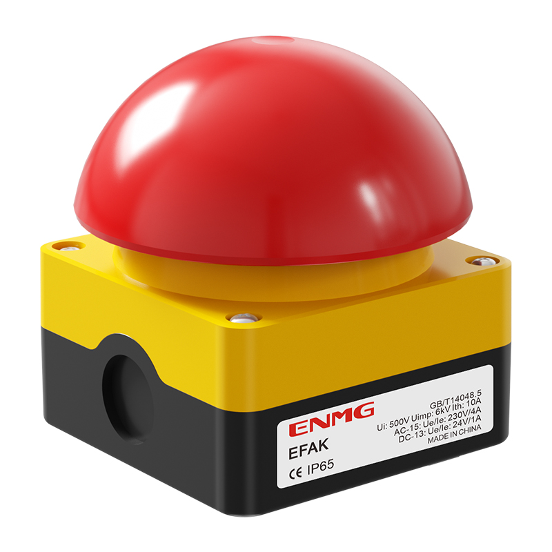
Five palm, elbow and foot-operated switch variants: four automatic-return colors and a red push-to-latch, pull-to-reset model on a yellow base. Compare operation, contacts and installation data in one place.
Request a quote ↗Email insteadPRODUCT PHOTOS
EFAK gallery
Select a photo to view the original image.
TECHNICAL DATA / EFAK
Specifications & selection.
- Large hemispherical actuator for palm, elbow or foot operation.
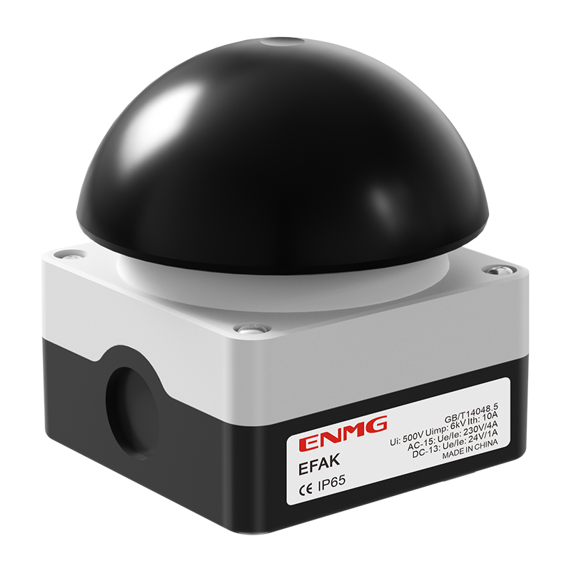
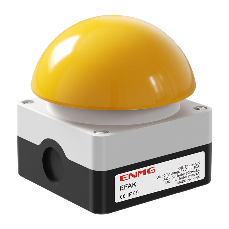
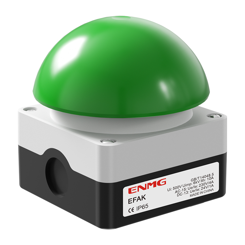
- Automatic-return models: black (S), yellow (Y), green (G) and red (R), on gray and black enclosures.
- V model: red actuator on a yellow and black enclosure; push to latch and pull to reset.
- All five listed models have 1 NO + 1 NC contacts.
- Ø92 mm nominal PC/ABS operating head; reinforced flame-retardant plastic enclosure; approximately 0.35 kg.
- IP65 enclosure rating with correctly fitted seals and cable glands.
| Order code | Actuator / base | Operation | Contacts | Force / frequency |
|---|---|---|---|---|
| EFAK-S/KC11/I | Black | Momentary / automatic return | 1 NO + 1 NC | 20–40 N / ≤3600 operations per hour |
| EFAK-Y/KC11/I | Yellow | Momentary / automatic return | 1 NO + 1 NC | 20–40 N / ≤3600 operations per hour |
| EFAK-G/KC11/I | Green | Momentary / automatic return | 1 NO + 1 NC | 20–40 N / ≤3600 operations per hour |
| EFAK-R/KC11/I | Red | Momentary / automatic return | 1 NO + 1 NC | 20–40 N / ≤3600 operations per hour |
| EFAK-R/V/KC11/IY | Red / yellow base | Push-to-latch / pull-to-reset | 1 NO + 1 NC | 40–60 N / ≤600 operations per hour |
| Parameter | Value |
|---|---|
| Thermal current Ith | 10 A; not an AC-15 / DC-13 switching rating |
| Insulation voltage Ui | 500 V |
| AC-15 | 4 A at 230 V |
| DC-13 | 1 A at 24 V |
| Contact material / initial resistance | Silver alloy / ≤100 mΩ |
| Insulation resistance | ≥100 MΩ at 500 VDC |
| Withstand | 1000 VAC between live parts; 2500 VAC to non-live parts; 50/60 Hz, 1 minute |
| Parameter | Value |
|---|---|
| Base / total height | 85 × 85 mm / 101 mm |
| Actuator | Ø92 mm nominal; approximately Ø94 mm outer crown |
| Mounting | 65 mm hole spacing; 2-R3.75 in source |
| Cable entry positions | Three side entries and one bottom entry; confirm gland thread |
| Wire | Solid 0.75–2.5 mm²; stranded 0.5–2.5 mm² |
| Terminal torque | 0.8 N·m |
| Ambient / storage | −25 to +80 °C / −30 to +120 °C; no condensation or icing |
| Humidity | ≤90% RH |
Selection & installation notes
- The four non-V models return automatically. It must not replace a latching emergency-stop device; the family’s pull-to-reset model has a separate V code.
- This V model is mechanically latching. Its suitability within a machine emergency-stop function requires verification of the exact contact mechanism and the complete safety circuit; no PL or SIL rating is established by this page.
- The source lists AC-15 230 V / 4 A and DC-13 24 V / 1 A. Its separate 10 A 250 VAC / 30 VDC statement is not used as a DC-13 rating.
- The page inconsistently labels cable entries as M20 and PG13.5 and gives an incompatible Ø5.5 mm opening. Confirm actual gland threads and cutouts before machining; M20 and PG13.5 are not interchangeable.
- IP65 does not establish high-pressure washer compatibility. The source’s 100 Pa high-pressure cleaning statement is inconsistent; obtain cleaning instructions before washdown.
- Seal unused entries, match glands to cable diameter and isolate power before wiring. The family brochure is provided for reference; request the current model-specific drawing when designing a machine.
Based on the official Chinese product page and selection charts ↗. Checked 2026-09-15. Confirm the current specification for the exact model when ordering.
TECHNICAL RESOURCES
Plan your integration.
ENMG control components — English product-family brochure.
This is a product-family brochure. Request a model-specific datasheet and installation drawing with your inquiry.