
ENMG / GUARD INTERLOCK SWITCHES
ESDL
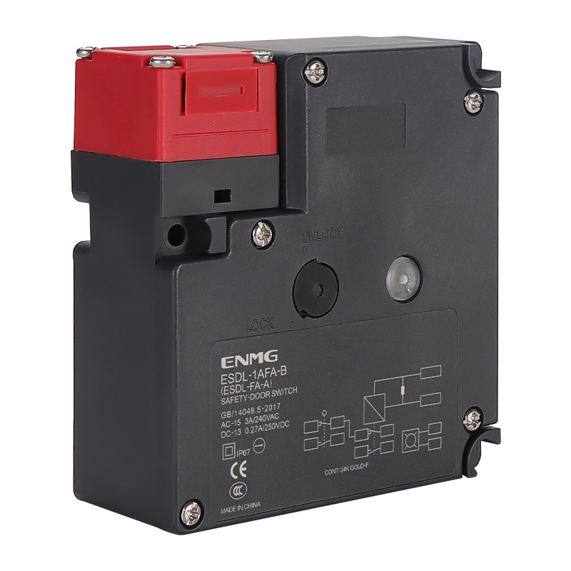
Guard-locking safety door switches
Actuator-operated guard switches with separate door and lock monitoring contacts, plastic or metal heads and selectable locking behaviour.
Request a quote ↗TECHNICAL DATA / ESDL
Specifications & selection.
- Slow-action contacts and separate door/lock monitoring.
- 24 VDC locking/release mechanism in the selection chart.
- Orange status indication and matched ESDS-K5 actuator.
| Plastic head | Metal head | Door contacts | Lock contacts |
|---|---|---|---|
| ESDL-1AFA-B | ESDL-1ADA-B | 1NC/1NO | 1NC/1NO |
| ESDL-1BFA-B | ESDL-1BDA-B | 1NC/1NO | 2NC |
| ESDL-1CFA-B | ESDL-1CDA-B | 2NC | 1NC/1NO |
| ESDL-1DFA-B | ESDL-1DDA-B | 2NC | 2NC |
| ESDL-1EFA-B | ESDL-1EDA-B | 2NC/1NO | 1NC/1NO |
| ESDL-1FFA-B | ESDL-1FDA-B | 2NC/1NO | 2NC |
| ESDL-1GFA-B | ESDL-1GDA-B | 3NC | 1NC/1NO |
| ESDL-1HFA-B | ESDL-1HDA-B | 3NC | 2NC |
| Plastic head | Metal head | Door contacts | Lock contacts |
|---|---|---|---|
| ESDL-1AFG-B | ESDL-1ADG-B | 1NC/1NO | 1NC/1NO |
| ESDL-1BFG-B | ESDL-1BDG-B | 1NC/1NO | 2NC |
| ESDL-1CFG-B | ESDL-1CDG-B | 2NC | 1NC/1NO |
| ESDL-1DFG-B | ESDL-1DDG-B | 2NC | 2NC |
| ESDL-1EFG-B | ESDL-1EDG-B | 2NC/1NO | 1NC/1NO |
| ESDL-1FFG-B | ESDL-1FDG-B | 2NC/1NO | 2NC |
| ESDL-1GFG-B | ESDL-1GDG-B | 3NC | 1NC/1NO |
| ESDL-1HFG-B | ESDL-1HDG-B | 3NC | 2NC |
| Parameter | Value |
|---|---|
| Contact load | AC-15: 3 A at 240 VAC; DC-13: 0.27 A at 250 VDC |
| Insulation voltage Ui | 300 V |
| Resistance / minimum load | ≤25 mΩ per contact / 1 mA at 5 VDC |
| Insulation resistance | ≥100 MΩ at 500 VDC |
| Operating speed | 0.05–0.5 m/s |
| Mechanical / electrical life | Over 1 million / 500,000 operations; test conditions not stated |
| Lock holding force | Up to 1300 N in source; verified design rating required |
| Insertion / withdrawal force | ≤15 / ≤30 N, with mechanism appropriately released |
| Operating ambient / humidity | −10 to +55 °C / <90% RH; no condensation or icing |
| Protection designation | IP65 / Class II in source |
| Approximate outline / mass | 106 × 50 × 110 mm / 360 g |
| Cable entry in naming image | PG11 |
Selection & installation notes
- The original selection image is used for contact combinations: its B/C/D/F mappings differ from the prose. Confirm the exact order-code circuit diagram before integrating the switch.
- The image defines A as mechanical locking/electromagnetic release and G as electromagnetic locking/mechanical release. They have different loss-of-power behaviour and are not interchangeable.
- The -B LED option is marked AC/DC 10–115 V in the naming image; this is not the 24 VDC actuator supply. The prose conflates these values and also mentions Pg13.5; confirm terminal and cable-entry drawings.
- The published force and life values do not establish a complete-machine safety performance level. Select, wire and validate the guard-interlocking system against the machine risk assessment and exact product documentation.
- Use a matched actuator, verify alignment and stopping conditions, and isolate hazardous energy before mechanical release or maintenance. Do not bypass the guard switch.
Based on the official Chinese product page and selection charts ↗. Checked 2026-09-15. Confirm the current specification for the exact model when ordering.
TECHNICAL RESOURCES
Plan your integration.
ENMG safety products — English product-family brochure.
This is a product-family brochure. Request a model-specific datasheet and installation drawing with your inquiry.