
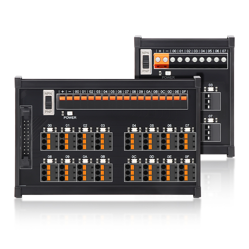
ENMG / SENSOR DISTRIBUTION MODULES
ESTB-P
Plug-in sensor interface terminal modules
DIN-mounted sensor wiring interfaces with pluggable sensor connectors, selectable NPN/PNP indication and screw or spring output connections.
Request a quote ↗TECHNICAL DATA / ESTB-P
Specifications & selection.
- 4, 8, 12, 16 and 32-point selection models.
- 12–24 VDC rated voltage; per-channel status indication.
- 35 mm DIN-rail or surface screw mounting.
| Points | Screw model | Spring model | L × W × H, screw / spring (mm) |
|---|---|---|---|
| 4 | ESTB-04SP1-3 | ESTB-04MP5-3 | 39.8 × 86.2 × 42.5 / 48.4 |
| 8 | ESTB-08SP1-3 | ESTB-08MP5-3 | 69.8 × 86.2 × 42.5 / 48.4 |
| 12 | ESTB-12SP1-3 | ESTB-12MP5-3 | 99.8 × 86.2 × 42.5 / 48.4 |
| 16 | ESTB-16SP1-3C | ESTB-16MP5-3C | 129.8 × 86.2 × 42.5 / 48.4 |
| 32 | ESTB-32SP1-3C | ESTB-32MP5-3C | 249.8 × 86.2 × 42.5 / 48.4 |
| Parameter | Value |
|---|---|
| Rated voltage / current | 12–24 VDC / 1 A; shared-path conditions require confirmation |
| Peak withstand current | 3 A; pulse duration not specified |
| Initial contact resistance | ≤50 mΩ |
| Dielectric withstand | 500 VAC, 50/60 Hz, 1 minute |
| Insulation resistance | 100 MΩ at 500 VDC |
| Ambient | +10 to +50 °C in original image; 45–85% RH; no condensation or icing |
| Indication | NPN green / PNP red; power LED |
| Polarity selection | NPN / PNP selector; match sensor and PLC input |
| Connection | Pitch / screw | Wire | Strip |
|---|---|---|---|
| Output screw | 5 mm / M2.5 | 24–12 AWG | 6–7 mm |
| Output spring | 5 mm | 22–12 AWG | 8–9 mm |
| Plug-in screw P1 | 3.81 mm / M2 | 28–16 AWG | 6–7 mm |
| Plug-in spring P5 | 3.81 mm | 28–16 AWG | 6–7 mm |
Selection & installation notes
- The naming image describes 3-wire and 4-wire options; the selection chart above lists -3 models. Confirm wiring before using a two-wire sensor mentioned in the introduction.
- C denotes the MIL connector option for 16/32-point variants. The 32-point family uses MIL output; verify the exact pin map and whether each terminal specification applies to the selected connector.
- The 3 A peak value is not a continuous rating. Confirm current per signal, sensor supply total and common-path limit; terminal wire capacity does not raise the module rating.
- This is a wiring interface; no input-to-output galvanic isolation is established by its dielectric test. Status LEDs do not prove correct sensor operation.
- De-energize before plugging, changing NPN/PNP selection or wiring. Match power polarity and unused pins to the exact production schematic.
Based on the official Chinese product page and selection charts ↗. Checked 2026-09-15. Confirm the current specification for the exact model when ordering.
TECHNICAL RESOURCES
Plan your integration.
ENMG wiring terminals — English product-family brochure.
This is a product-family brochure. Request a model-specific datasheet and installation drawing with your inquiry.