
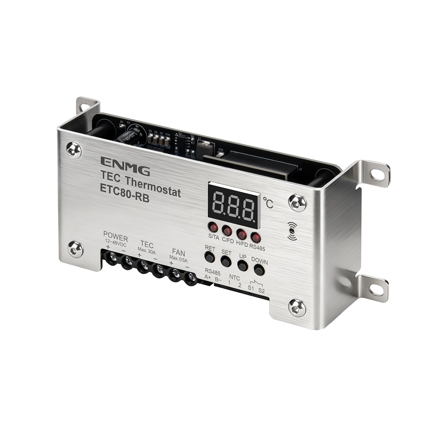
ENMG / TEMPERATURE CONTROLLERS
ETC80
Thermoelectric heating and cooling controllers
Controllers for TEC assemblies with temperature sensing, fan output and serial communication. Relay and H-bridge versions require separate selection and commissioning.
Request a quote ↗TECHNICAL DATA / ETC80
Specifications & selection.
- R: relay switching; H: MOSFET H-bridge control.
- B: semi-enclosed body; P: panel version.
- NTC temperature input and external overtemperature input.
| Variant | Supply stated in current prose | Outline L × W × H |
|---|---|---|
| ETC80-RB | 12–24 VDC | 150 × 60 × 34 mm |
| ETC80-RP | 12–24 VDC | 120 × 60 × 47.2 mm |
| ETC80-HB | 12–48 VDC | 150 × 60 × 31.1 mm |
| ETC80-HP | 12–48 VDC | 120 × 60 × 43.1 mm |
| Parameter | Published information |
|---|---|
| TEC / fan output | Up to 30 A / 0.5 A; verify exact variant, cooling and continuous-load conditions |
| Controller consumption | <4 W, excluding external loads |
| Display / control range | −40 to +150 °C / −40 to +120 °C |
| H-bridge control | 1 kHz PWM; 500 ms PID control cycle; 1 s reversal dead time, current prose |
| H command scale | −1000 to +1000 ‰; negative cooling, positive heating, zero off |
| H internal resolution | 0.01 °C calculation resolution; not measurement accuracy |
| Sensor / thermal interlock | NTC / S1–S2 normally closed overtemperature input |
| Mounting | RB: side slots and M4 points; RP: four M4 positions, 105 × 45 mm centers in original drawing |
| HB / HP mass in prose | 0.1267 / 0.0985 kg; R mass unavailable |
| Topic | Current prose | Original illustrated instructions |
|---|---|---|
| Communication | RS485 Modbus RTU, 9600, 8N1 | Custom AA…55 framing and additive checksum |
| Menu | E1/E2 start limits, E3 alarm, E4 offset, E5 address | E1/E2 starts; E3/E4 hysteresis; E5 alarm; E6 fan delay; E7 offset |
| R supply marking | 12–24 VDC in selection prose | RP drawing face is marked 12–48 VDC |
Selection & installation notes
- The source contains different controller revisions and incompatible communication/menu descriptions. Request the firmware-specific manual and protocol before connecting a PLC. Do not use the illustrated proprietary frames as Modbus messages.
- Do not apply the H-bridge PWM/PID parameters to a relay version. Confirm input voltage on the exact delivered controller before powering it.
- Use independent overcurrent and thermal protection for the complete TEC assembly. Connect the S1/S2 interlock as approved; a factory short is not an active thermal protector.
- Size the DC supply, cables, connectors and heat sinks for actual TEC current and heat rejection. The 30 A family headline alone does not establish continuous capacity under all ambient conditions.
- Published −10 to +90 °C controller ambient needs revision-specific confirmation. Control-range and numerical resolution values are not accuracy or operating-ambient specifications.
Based on the official Chinese product page and selection charts ↗. Checked 2026-09-15. Confirm the current specification for the exact model when ordering.
TECHNICAL RESOURCES
Plan your integration.
ENMG cabinet environment systems — English product-family brochure.
This is a product-family brochure. Request a model-specific datasheet and installation drawing with your inquiry.