
ENMG / CONNECTOR INTERFACE MODULES
EXTB
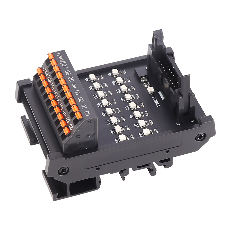
MIL I/O terminal modules with LED indication
Connector-to-terminal interfaces for PLC and control-board wiring, with individual signal LEDs and a power indicator.
Request a quote ↗TECHNICAL DATA / EXTB
Specifications & selection.
- 20-pin version: 16 signal points; 40-pin version: 32 signal points.
- NPN common-positive and PNP common-negative versions.
- Screw or spring terminals on a 35 mm DIN base.
| Connector class | Polarity | Screw model | Spring model | L × W × H (mm) |
|---|---|---|---|---|
| 20 pins | NPN / COM+ | EXTB-C20NS-L | EXTB-C20NM-L | 59 × 87 × 52 |
| 20 pins | PNP / COM− | EXTB-C20PS-L | EXTB-C20PM-L | 59 × 87 × 52 |
| 40 pins | NPN / COM+ | EXTB-C40NS-L | EXTB-C40NM-L | 109 × 87 × 52 |
| 40 pins | PNP / COM− | EXTB-C40PS-L | EXTB-C40PM-L | 109 × 87 × 52 |
| Parameter | Published value |
|---|---|
| MIL20 signal labels | 00–0F: 16 signals plus common/unused pins |
| MIL40 signal labels | 00–1F: 32 signals plus common/unused pins |
| Module current | 1 A; confirm per-path and shared-COM conditions |
| Voltage in general technical image | 125 VAC / 30 VDC; LED supply compatibility requires separate confirmation |
| Withstand | 500 VAC, 50/60 Hz, 1 minute |
| Insulation resistance | 100 MΩ at 500 VDC |
| Connector pitch | 2.54 mm |
| Ambient | −10 to +50 °C; 45–85% RH; no condensation or icing |
| Parameter | Screw | Spring |
|---|---|---|
| Component capacity | 10 A / 300 V | 15 A / 300 V |
| Wire | 22–12 AWG | 22–16 AWG (1.5 mm² in source) |
| Strip | 6–7 mm | 8–9 mm |
| Screw / torque | M2.5 / 0.4 N·m | Not applicable |
| Pitch | 5 mm | 5 mm |
Selection & installation notes
- A 20/40 channel label refers to connector class, not 20/40 usable I/O signals. Match every pin against the exact board cable and NPN/PNP schematic; leave NC unused pins unconnected.
- The pictured LEDs and common terminals are marked +24 V. The 125 VAC general rating does not establish that mains can be applied to the LED circuits; confirm intended DC signal and indicator supply limits.
- This is a wiring adapter. The withstand test does not establish galvanic isolation between each input pin and its corresponding output terminal.
- Terminal component ratings do not raise the 1 A module limit. Confirm aggregate common current and driver compatibility. LED state indicates signal level, not verified load operation. Isolate power before connector removal.
Based on the official Chinese product page and selection charts ↗. Checked 2026-09-15. Confirm the current specification for the exact model when ordering.
TECHNICAL RESOURCES
Plan your integration.
ENMG wiring terminals — English product-family brochure.
This is a product-family brochure. Request a model-specific datasheet and installation drawing with your inquiry.