
ENMG / SIGNAL CONVERTERS
HTL / TTL
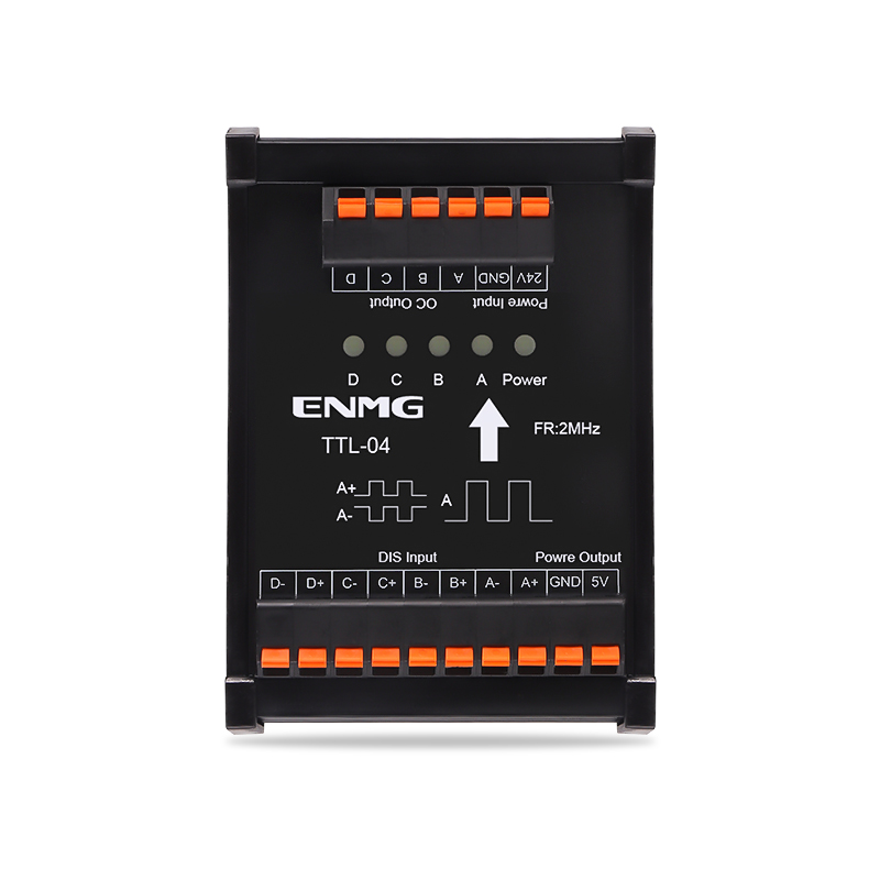
Differential and single-ended signal converters
DIN-rail interface modules for matching encoder and pulse signals to PLC and motion-controller inputs. Choose a specific conversion direction and signal level.
Request a quote ↗TECHNICAL DATA / HTL / TTL
Specifications & selection.
- TTL: differential input to single-ended output, 2–4 channels.
- HTL: single-ended input to differential output, 4 channels.
- Screw, spring and pluggable screw terminals.
| Direction | Channels | Screw / spring / pluggable |
|---|---|---|
| Differential to single-ended | 2 | TTL-02S-L / TTL-02M-L / TTL-02P-L |
| Differential to single-ended | 3 | TTL-03S-L / TTL-03M-L / TTL-03P-L |
| Differential to single-ended | 4 | TTL-04S-L / TTL-04M-L / TTL-04P-L |
| Single-ended to differential | 4 | HTL-04S-L / HTL-04M-L / HTL-04P-L |
| Parameter | Value |
|---|---|
| Working supply | 24 VDC |
| TTL differential input | 5 V Vpp standard; 1.8 / 3.3 / 12 / 24 V by specification |
| HTL single-ended input | 24 VDC |
| TTL auxiliary output supply | 5 V, 1 A; not the signal output current |
| Maximum response frequency | 2 MHz; confirm cable length and waveform conditions |
| Base / mounting | -L black 72 mm base / 35 mm DIN rail |
| Ambient | −10 to +50 °C; 5–85% RH, no condensation or icing |
| Screw / pluggable terminals | M3, pitch 5 mm; 22–12 AWG; 0.5 N·m; strip 6–7 mm |
| Spring terminals | Pitch 5 mm; 22–16 AWG; strip 8–10 mm |
Selection & installation notes
- The current prose describes a wider 4.5–28 V supply, −20 to +60 °C ambient and push-pull output, while the original chart specifies 24 VDC, −10 to +50 °C and describes collector output. These specifications must not be combined into one guaranteed variant. Confirm the ordered hardware revision, output circuit and supply arrangement.
- The prose also quotes optocoupler isolation ≥5 kVrms, ≤0.5 µs delay and ±0.5 A drive. These are not confirmed complete-module ratings in the original selection chart; request the model-specific datasheet.
- A module is directional, not automatically bidirectional. Specify input waveform, differential/single-ended interface, logic amplitude, polarity and target receiver before ordering.
- Keep signal output current separate from the listed 5 V auxiliary supply capacity. Verify grounding, shielding and termination with the approved wiring diagram.
Based on the official Chinese product page and selection charts ↗. Checked 2026-09-15. Confirm the current specification for the exact model when ordering.
TECHNICAL RESOURCES
Plan your integration.
ENMG control components — English product-family brochure.
This is a product-family brochure. Request a model-specific datasheet and installation drawing with your inquiry.