
ENMG / SOLID-STATE INTERFACES
MT-L
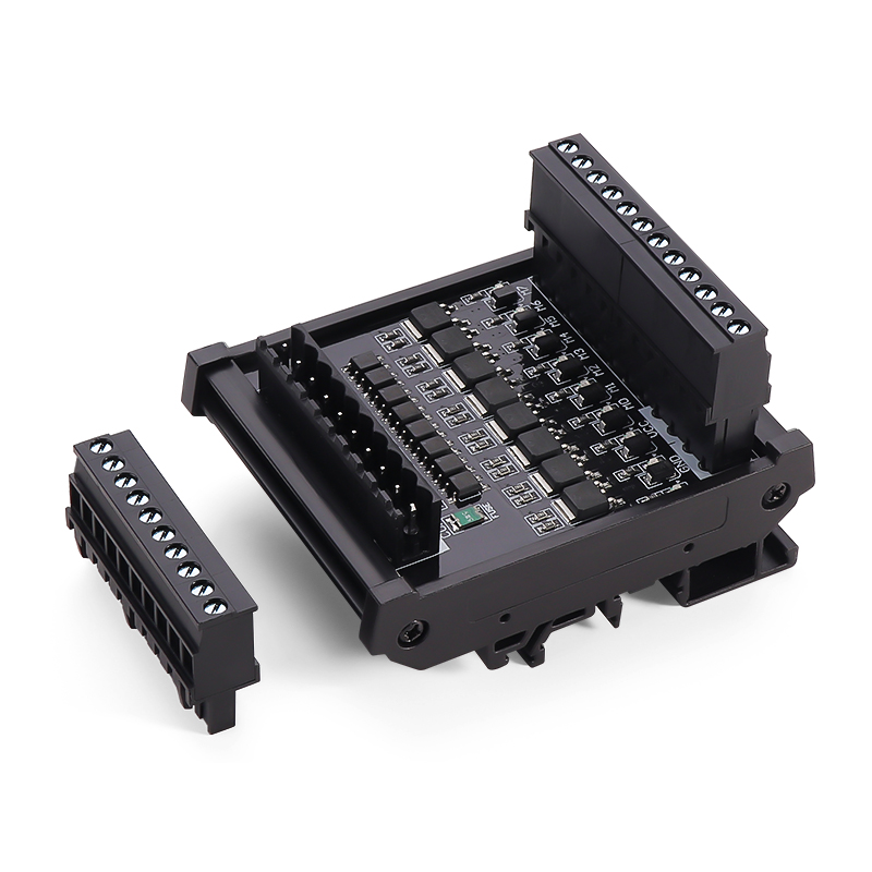
Optically isolated MOSFET output modules
Multi-channel DC switching interfaces with non-polarized control inputs and COM− load outputs for PLC applications.
Request a quote ↗TECHNICAL DATA / MT-L
Specifications & selection.
- 4, 8 and 16 channels; screw, spring and plug-in terminal options.
- Optical isolation, input resettable fuse and TVS, with output flyback and RC protection described by the source.
- Red LED indication and 35 mm DIN-rail mounting.
| Channels | Screw | Spring | Plug-in |
|---|---|---|---|
| 4 | MT04S-L | MT04M-L | MT04P-L |
| 8 | MT08S-L | MT08M-L | MT08P-L |
| 16 | MT16S-L | MT16M-L | MT16P-L |
| Parameter | Specification |
|---|---|
| Control input | 24 VDC in technical text; selection chart states 5–24 VDC — confirm exact variant |
| Load output | 12–24 VDC; COM− |
| Peak output voltage | 60 V peak; not a continuous operating voltage |
| Load current | 3 A per channel; total module current ≤10 A |
| Surge current | 20 A; duration and repetition not specified |
| ON-state voltage drop | 0.3 V |
| OFF-state leakage | Maximum 1 mA |
| Operate / release | ≤1 ms / ≤1 ms |
| Isolation | 3750 V; test duration not stated |
| Ambient | −40 to +70 °C, no condensation or icing; 5–85% RH |
| Reference temperature | 25 °C |
| Item | Published information |
|---|---|
| 4-channel outline | Selection: 48 × 85 × 40 mm; outline: 40 × 85 × 40 mm — confirm |
| 8-channel outline | 70 × 85 × 40 mm |
| 16-channel outline | 130 × 85 × 40 mm |
| Terminal variants | S: screw; M: spring; P1: top-entry plug; P2: side-entry plug; confirm full order code |
| Barrier-terminal data in text | M3, 8 mm pitch, wire ≤1.25 mm², 1.2 N·m — do not apply to every variant |
| Other drawing annotations | Screw/spring: 39 × 87 mm; plug-in: 55 × 87 mm; axes/variant applicability unclear |
| Dimensional tolerance | Source states ±1 mm |
Selection & installation notes
- Do not select from the 5–24 VDC input range without confirming the ordered module; the same page specifies 24 VDC elsewhere.
- The source describes S/S at 0 V for positive input signals and 24 V for negative input signals. Verify the exact NPN/PNP diagram and terminal labels.
- Confirm the 4-channel outline and terminal-specific wire size, strip length and torque before cabinet layout.
- Assess fuse coordination, inrush, thermal derating above 40 °C and suppression for the actual load. Built-in protection is not a universal substitute for external circuit protection.
- OFF-state leakage remains present; isolate the load supply before wiring or service. The 20 A surge figure lacks a time condition and must not be treated as a continuous rating.
Based on the official Chinese product page and selection charts ↗. Checked 2026-09-15. Confirm the current specification for the exact model when ordering.
TECHNICAL RESOURCES
Plan your integration.
ENMG relays — English product-family brochure.
This is a product-family brochure. Request a model-specific datasheet and installation drawing with your inquiry.