
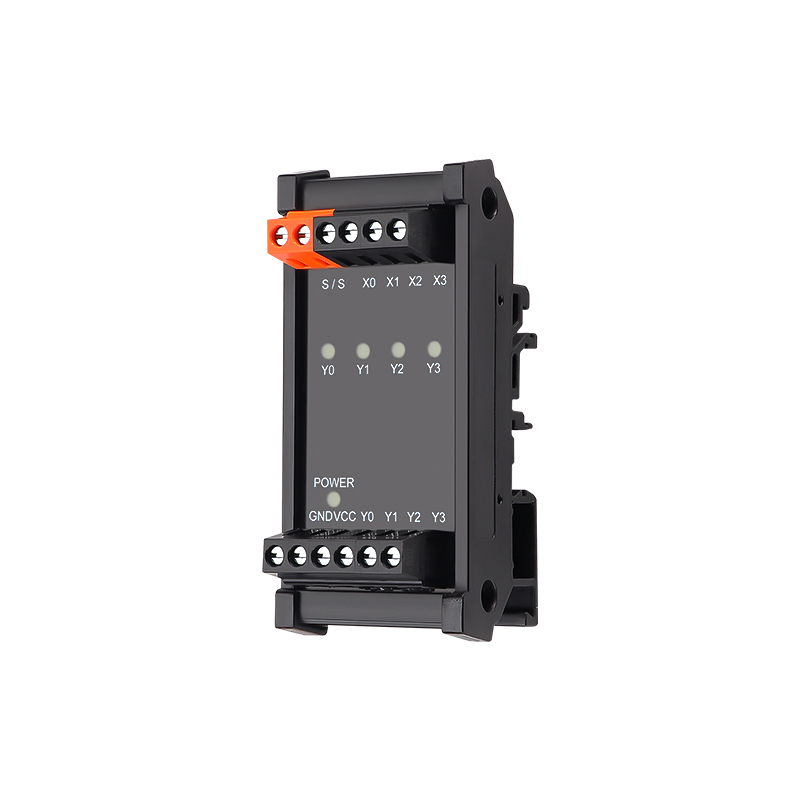
ENMG / PLC INTERFACES
MT04 / MT08 / MT16
Optically isolated MOSFET interface modules
Solid-state PLC signal amplifier modules for switching DC loads such as solenoid valves, indicator lamps and relays. Available with 4, 8 or 16 channels and three terminal styles.
Request a quote ↗TECHNICAL DATA / MT04 / MT08 / MT16
Specifications & selection.
- Optocoupler isolation with enhancement-mode MOSFET outputs and flyback diodes.
- Input protection includes a resettable fuse and transient suppression, with red channel indicators.
- Screw, spring and pluggable terminal options; 35 mm DIN rail mounting.
| Channels | Cage screw | Spring | Pluggable | L × W × H (mm) |
|---|---|---|---|---|
| 4 | MT04S-L | MT04M-L | MT04P-L | 48 × 85 × 40 |
| 8 | MT08S-L | MT08M-L | MT08P-L | 70 × 85 × 40 |
| 16 | MT16S-L | MT16M-L | MT16P-L | 130 × 85 × 40 |
| Parameter | Specification |
|---|---|
| Output working voltage | 12–24 VDC |
| Peak withstand voltage | 60 VDC; not a continuous operating rating |
| Per-channel load current | 3 A maximum |
| Total common-terminal current | 10 A maximum |
| Non-repetitive surge current | 20 A; duration not specified |
| On-state voltage drop | 0.3 V |
| Output leakage | 1 mA maximum |
| Turn-on / turn-off time | 1 ms maximum |
| Input control voltage | 24 VDC in the technical table; selection note says 5–24 VDC — confirm exact model |
| Input polarity | COM+/−; NPN/PNP input support |
| Output polarity | COM− or COM+ options; confirm ordered version |
| Input-to-output isolation | 3,750 V; test duration not specified |
| Output protection | Built-in flyback diode |
| Parameter | Specification |
|---|---|
| S/S | Input common; 0 V for positive-output signals, 24 V for negative-output signals in the source example |
| Dual S terminals | One common connection plus a connection for extending to another module |
| X / Y labels | Input / output signals; numbering follows the module label |
| GND / VCC | DC supply |
| Operating temperature | −40 to +70°C; no condensation or ice |
| Humidity | 5–85% RH |
| Mounting | 35 mm DIN rail |
| Reference test temperature | 25°C unless stated otherwise |
| Weight | Not specified |
Selection & installation notes
- Respect both limits simultaneously: 3 A per output and 10 A total at the common terminal. Derate from 40°C upward and provide ventilation.
- Use semiconductor fast-fuse protection and suitable surge suppression; allow current margin for inductive or capacitive loads. Isolate the main supply before servicing.
- The source mixes a barrier-terminal specification (M3, 8 mm pitch, ≤1.25 mm², 1.2 N·m) with cage/spring/pluggable model tables. Do not apply that torque or wire size to these variants without confirmation.
- The 16-channel selection row specifies COM− output, while the general description offers either polarity. Confirm the exact output version.
- The source outline table gives the dimensions above, while separate annotations give approximately 39/87 mm. Obtain the exact terminal-variant drawing before layout.
- Ordering codes are not freely interchangeable. Confirm the full part number, input range, output polarity and terminal style.
Based on the official Chinese product page and selection charts ↗. Checked 2026-09-15. Confirm the current specification for the exact model when ordering.
TECHNICAL RESOURCES
Plan your integration.
ENMG wiring terminals — English product-family brochure.
This is a product-family brochure. Request a model-specific datasheet and installation drawing with your inquiry.