
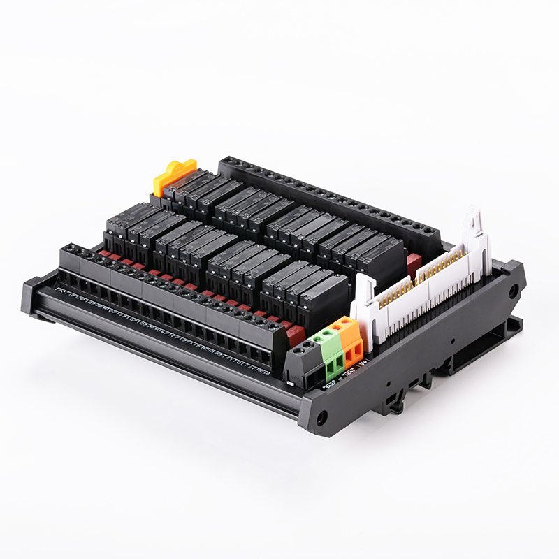
ENMG / RELAY INTERFACES
RT-P32CS-X
32-channel fused relay interface modules
Wide-base relay interfaces with a 40-pin MIL input, grouped mechanical relay outputs and replaceable relays for PLC wiring.
Request a quote ↗TECHNICAL DATA / RT-P32CS-X
Specifications & selection.
- 32 outputs grouped four points per common.
- Non-polarized NPN/PNP input with coil TVS protection and red/green indication.
- 5 A / 250 V time-delay output fuses specified by the source.
| Relay family | Screw output | Spring output | L × W × H |
|---|---|---|---|
| PA-N | RT-P32CS-X | RT-P32CM-X | 135 × 120 × 52 mm |
| APAN | RT-E32CS-X | RT-E32CM-X | 135 × 120 × 52 mm |
| Parameter | Specification |
|---|---|
| Relay choices | PA-N for P models; APAN3124 / APAN3112 / APAN3105 for E models |
| Contact arrangement | Normally open 1a; source describes PA-N as twin-contact |
| Contact material | Silver-nickel alloy; PA-N gold plating stated |
| Initial contact resistance | Maximum 30 mΩ |
| Rated load stated | 5 A at 250 VAC / 30 VDC; confirm exact relay and load category |
| Mechanical / electrical life | ≥20 million / ≥100,000 operations; test load/frequency not provided |
| Coil voltage | 5 / 12 / 24 VDC; default 24 VDC |
| Maximum coil voltage | 120% of rated voltage; continuous suitability not established |
| Operate / release thresholds | 70% / 5% of rated voltage in source |
| Coil power per circuit | 110 mW |
| Operate / release time | 10 ms / 5 ms |
| Parameter | Specification |
|---|---|
| Input overcurrent protection | 500 mA resettable fuse |
| Input connector | DC2-2.54-40PS, MIL 40-pin |
| Output grouping | Four points per COM; verify group and total load current |
| Screw terminals | M2.5, 5.0 mm pitch; component rating 10 A / 300 V; 22–12 AWG; 0.4 N·m; strip 6–7 mm |
| Spring variant terminals | 5.0 mm pitch; component rating 10 A / 300 V; 22–12 AWG; strip 6–7 mm |
| Base / installation | 105 mm base; 35 mm DIN rail; no surface-screw installation for advanced version |
| Ambient | −40 to +70 °C; no condensation or icing |
| Humidity | 5–85% RH |
| Dielectric withstand | 2500 VAC / 1 minute |
| Source markings/claims | IP20, UL94 V-0, CE; supporting documents not supplied on page |
| Mass | Not specified |
| Base | Board width | Example | L × W × H |
|---|---|---|---|
| L | 72 mm | RT-P32S-L / RT-P32M-L | 220 × 87 × 50 mm |
| X | 105 mm | RT-P32CS-X / RT-P32CM-X | 135 × 120 × 52 mm |
Selection & installation notes
- The 5 A per-relay figure does not establish four-times-5 A capacity at each common terminal. Confirm group current, fuse topology and simultaneous-channel limits.
- At low coil voltage, confirm the input supply and resettable-fuse grouping for all 32 channels; total demand cannot be inferred from a single coil rating alone.
- Verify the PLC cable pinout and common polarity. The -1 suffix identifies a different MIL connector orientation and requires an exact drawing.
- Use correctly rated replacement fuses and confirm AC/DC breaking capacity; never replace with a higher rating or bypass.
- Isolate both control and load supplies before service; derate and suppress inductive loads. Request supporting conformity documents where required.
Based on the official Chinese product page and selection charts ↗. Checked 2026-09-15. Confirm the current specification for the exact model when ordering.
TECHNICAL RESOURCES
Plan your integration.
ENMG wiring terminals — English product-family brochure.
This is a product-family brochure. Request a model-specific datasheet and installation drawing with your inquiry.