
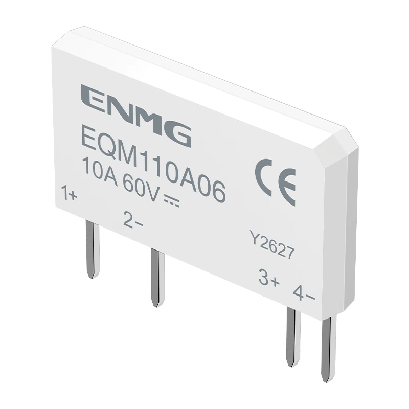
OPTO-RELAY / DC MOSFET
EQM110A06-S
Optically isolated MOSFET solid-state relay
EQM110A06-S optically isolated PCB relay. Review output topology, SIP4 package, application limits and request model-specific technical documents.
Request application review ↗Model specifications
Existing product data is provided for initial selection. Verify the latest model-specific datasheet and operating conditions before design-in. Listed limits are not unconditional operating ratings.
| Parameter | Specification | Condition / limit |
|---|---|---|
| Output topology | Single MOSFET, DC | |
| Package | SIP4 | Confirm the approved pinout and footprint. |
| Recommended LED current | 10–18 mA | Current-limited LED drive; confirm driver capability. |
| Isolation test | 3000 Vrms | AC, 1 minute; not a continuous working-voltage rating. |
| Current capability | Application review required | Confirm continuous current, cooling and duty cycle with ENMG. |
| Output blocking voltage | 60 V peak | Off-state limit; allow transient margin. Not a nominal system-voltage rating. |
Operating boundaries
Observe DC output polarity. A single MOSFET does not provide bidirectional blocking.
- The input is an LED, not a voltage-rated 24 V control port. Use a current-limited driver or calculate R = (Vin − VF) / Iin, including resistor power, voltage tolerance and GPIO capacity.
- Blocking voltage is not a recommended nominal working voltage. Allow transient margin; 60 V peak corresponds mathematically to 42.4 Vrms for a sine wave before any margin, not an unconditional 42 VAC system rating.
- Only the back-to-back MOSFET variant supports bidirectional blocking. Single-MOSFET versions have a body diode and require the specified DC output polarity.
- Conduction loss for MOSFETs is approximately I²Ron and rises with temperature. Meet both package power and junction-temperature limits; headline current is conditional on thermal design.
- Millisecond switching times do not support arbitrary high-frequency PWM. Zero-cross TRIAC types require AC current commutation and are not DC switches or standalone phase controllers.
- Verify the exact package drawing, PCB creepage, insulation category and solder profile. Isolation-test voltage is not continuous working voltage.
- Fit load-appropriate suppression and protection; a DC flyback diode is placed across the inductive load with correct polarity, not indiscriminately across the switch.
Package and pinout
SIP4. Request the approved dimension drawing, pin assignment and soldering conditions for this full model code. Do not infer terminal assignments from the illustration.
Technical documents
The English relay brochure covers the product family. Request the current EQM110A06-S datasheet and drawing with your application details.
Download English family brochure — YZ26I10 ↓Request model datasheet →Confirm model-specific conformity documentation and supply status with ENMG. Product markings alone do not establish certification scope.
Source and revision
Model reference: ZGC26H228 V1.1. Page knowledge revision: 2026-10-24.
The reference version below identifies the model document reviewed for this page. It does not replace an approved application-specific specification. Fields marked for confirmation remain pending.
Application questions
Can I connect the input directly to a voltage source?
Use a current-limited LED driver. Check source voltage, LED current and driver capability against the model datasheet.
Can the listed current be used at any ambient temperature?
No. Confirm ambient temperature, mounting, cooling, duty cycle and dissipation limits for your application.
Does the isolation test voltage equal the continuous working voltage?
No. Isolation test voltage is a specified test condition. Confirm the continuous working voltage, insulation requirements and PCB layout for the application.