
ENMG / THERMOELECTRIC COOLING
HETA-F
External Peltier enclosure air conditioner
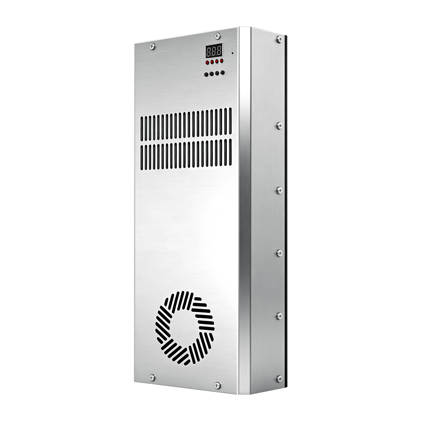
An externally mounted cabinet air conditioner with an integrated temperature controller and power supply. Its slim stainless-steel enclosure includes axial-fan heat dissipation and condensate collection provisions.
- Model family
- HETA-F
- Technology
- Peltier thermoelectric cooling
- Configuration
- External wall mounting
View technical specifications ↓
Send your operating conditions and quantity for model selection, specifications and a quotation.
ENGINEERING DATA / HETA-F
Specifications & selection.
Product overview
HETA-F is the external surface-mounted configuration of the HETA air-to-air cabinet cooling family. The following capacity, electrical and heat-sink data describe the HETA family; the exact F configuration must be selected for the cabinet and heat load.
- Solid-state Peltier cooling without a compressor or refrigerant.
- Cooling and heating through controlled reversal of TEC current, using a compatible controller.
- TEC1-127xx elements are the standard platform; TEC2, TES1 and TEC1-199 options are listed in the source catalogue.
- Heat-sink, capacity and voltage combinations can be discussed for custom assemblies.
- The cabinet seal must be maintained during installation; the source does not specify a numerical IP rating for the complete unit.
Technical specifications
| Parameter | Published specification |
|---|---|
| Published family capacity catalogue | 53–1064 W; 32 combinations of 8 base capacities and 4 element counts |
| Supply platforms | 12 / 24 / 48 VDC; depends on the selected assembly |
| TEC array limit | Up to 4 in series × 4 in parallel; 16 elements maximum |
| Element counts | 1 / 2 / 4 / 8 / 16 |
| Single-element maximum temperature difference | ≥66 °C; TEC2-19010 two-stage option: ≥80 °C |
| Heating / cooling | Bidirectional with a suitable reversing controller |
| Standard heat-sink codes | 101 / 102 / 151 / 152 / 153 / 154 / 156 |
| Source test condition | 25 °C ambient unless otherwise stated |
| Family installation codes | T / TS / TP / F / H / no suffix (tabletop) |
| Complete-unit dimensions and weight | Not specified in the source tables; obtain the selected model drawing |
| Complete-unit IP rating | Not specified in the source tables |
Capacity values are the published series catalogue ratings, not electrical input power or a guaranteed cooling result at every operating condition. The single-element temperature difference is not the cabinet or liquid temperature reduction. Select against heat load, ambient temperature and the model performance data.
Model selection
The Chinese HETA, HETA-F and HETA-TP pages publish the same TP selection examples. These rows are TP configurations, not confirmed F model combinations; request the F-specific drawing and electrical specification for an external unit.
| Model | Heat sink W × L (mm) | Cooling capacity (W) | Supply (VDC) |
|---|---|---|---|
| HETA-101TP-075 | 100 × 150 | 75 | 12 |
| HETA-151TP-106 | 150 × 200 | 106 | 24 |
| HETA-102TP-150 | 100 × 215 | 150 | 24 |
| HETA-153TP-300 | 150 × 400 | 300 | 48 |
| HETA-154TP-424 | 300 × 300 | 424 | 48 |
| HETA-156TP-600 | 300 × 400 | 600 | 48 |
Dimensions in this table refer to the hot-side heat-exchange surface, not the overall enclosure or the cabinet cutout. Earlier model names omit the voltage suffix; use the corresponding technical specification to confirm supply voltage.
How to read the model code
HETA – [heat-sink code][installation code] – [capacity W] – [voltage]
Published example: HETA-153TP-300-48V
| Field | Meaning |
|---|---|
| Series | HETA — air to air |
| Heat-sink code | 101, 102, 151, 152, 153, 154 or 156 |
| Installation code | T, TS, TP, F, H, or omitted for tabletop |
| Capacity code | 053 to 1064, in W; leading zero retained for values below 100 |
| Voltage suffix | 12V / 24V / 48V |
For HETA-F, the installation field is F; for HETA-TP, it is TP. The suffix identifies the configuration within the HETA family.
Heat-sink dimensions
| Code | Width (mm) | Length (mm) | Construction |
|---|---|---|---|
| 101 | 100 | 150 | Single heat sink |
| 102 | 100 | 215 | Single heat sink |
| 151 | 150 | 200 | Single heat sink |
| 152 | 150 | 300 | Single heat sink |
| 153 | 150 | 400 | Single heat sink |
| 154 | 300 | 300 | Two 152 heat sinks side by side |
| 156 | 300 | 400 | Two 153 heat sinks side by side |
Codes 154 and 156 use double-width assemblies. Code 155 is not listed. Complete assembly dimensions, weight and mounting cutouts must be checked against the selected model drawing.
Installation configurations
| Code | Configuration |
|---|---|
| T | Basic through-wall installation |
| TS | Through-wall; enhanced external fan protection |
| TP | Through-wall; enhanced internal and external fan protection |
| F | External surface-mounted installation |
| H | Flush, recessed installation |
| No code | Tabletop arrangement |
Cooling-capacity catalogue
| 1 element | 2 elements | 4 elements | 8 elements |
|---|---|---|---|
| 053 | 106 | 212 | 424 |
| 062 | 124 | 248 | 496 |
| 075 | 150 | 300 | 600 |
| 080 | 160 | 320 | 640 |
| 088 | 176 | 352 | 704 |
| 097 | 194 | 388 | 776 |
| 106 | 212 | 424 | 848 |
| 133 | 266 | 532 | 1064 |
The source defines 32 combinations, including repeated wattage values. Its 1064 W upper catalogue value uses eight TEC1-12715 elements. The array limit of 16 elements is a separate configuration limit, not an additional published capacity row.
Supply and TEC configuration
| Suffix | Source configuration |
|---|---|
| 12V | One 12 V-class element, or 2 / 4 elements in parallel |
| 24V | Two 12 V-class elements in series; alternatively a single or parallel 24 V-class TES1-24106 / TEC1-19911 arrangement |
| 48V | Four 12 V-class elements in series; 4-series × 2-parallel (8 elements) or 4-series × 4-parallel (16 elements) |
Match the assembly nameplate voltage and polarity. Do not mix different TEC element models within one assembly.
Compatible temperature controllers
| Controller | Output / interface | Source selection guidance | Listed control accuracy |
|---|---|---|---|
| ETC80-RB | Relay output / dry contact | Below 24 V AND below 10 A | ±0.5 °C |
| ETC80-HB | H-bridge MOSFET; PWM; reverse heating; RS485 | 212 W and above | ±0.1 °C |
For the 150–212 W transition range, check both voltage and current. The source recommends ETC80-HB at 212 W and above. These are controller accuracy figures; achieved system temperature uniformity and stability also depend on the sensor, load and installation.
Installation and operation
- Use the selected model cutout drawing for through-wall installation and seal the cabinet opening.
- Keep hot-side inlet and exhaust airflow unobstructed; prevent hot exhaust recirculating toward the cold-side inlet.
- Keep condensate drains clear when cold surfaces operate below the dew point.
- Provide maintenance access; avoid direct solar exposure and surrounding heat sources.
- Stop power immediately if required heat rejection fails, including fan failure or loss of liquid circulation. Continued operation can permanently damage the TEC elements.
- Use the nameplate supply and the correct polarity. Heating mode also requires normal heat rejection.
- Clean air-cooled heat-sink fins and filters regularly; service coolant on liquid-circuit assemblies.
- Disconnect power and store dry when unused for long periods.
Translated from the official Chinese product details ↗, checked 14 September 2026. Downloaded PDF editions retain their printed revision dates; confirm the applicable specification when ordering.
TECHNICAL RESOURCES
Plan your integration.
English cabinet environment brochure · YZ26I10
Confirm the exact variant, supply voltage, dimensions and operating conditions with our team before ordering.
Official product reference (Chinese) ↗SELECT YOUR COOLING APPROACH