
ENMG / THERMOELECTRIC COOLING
HETL
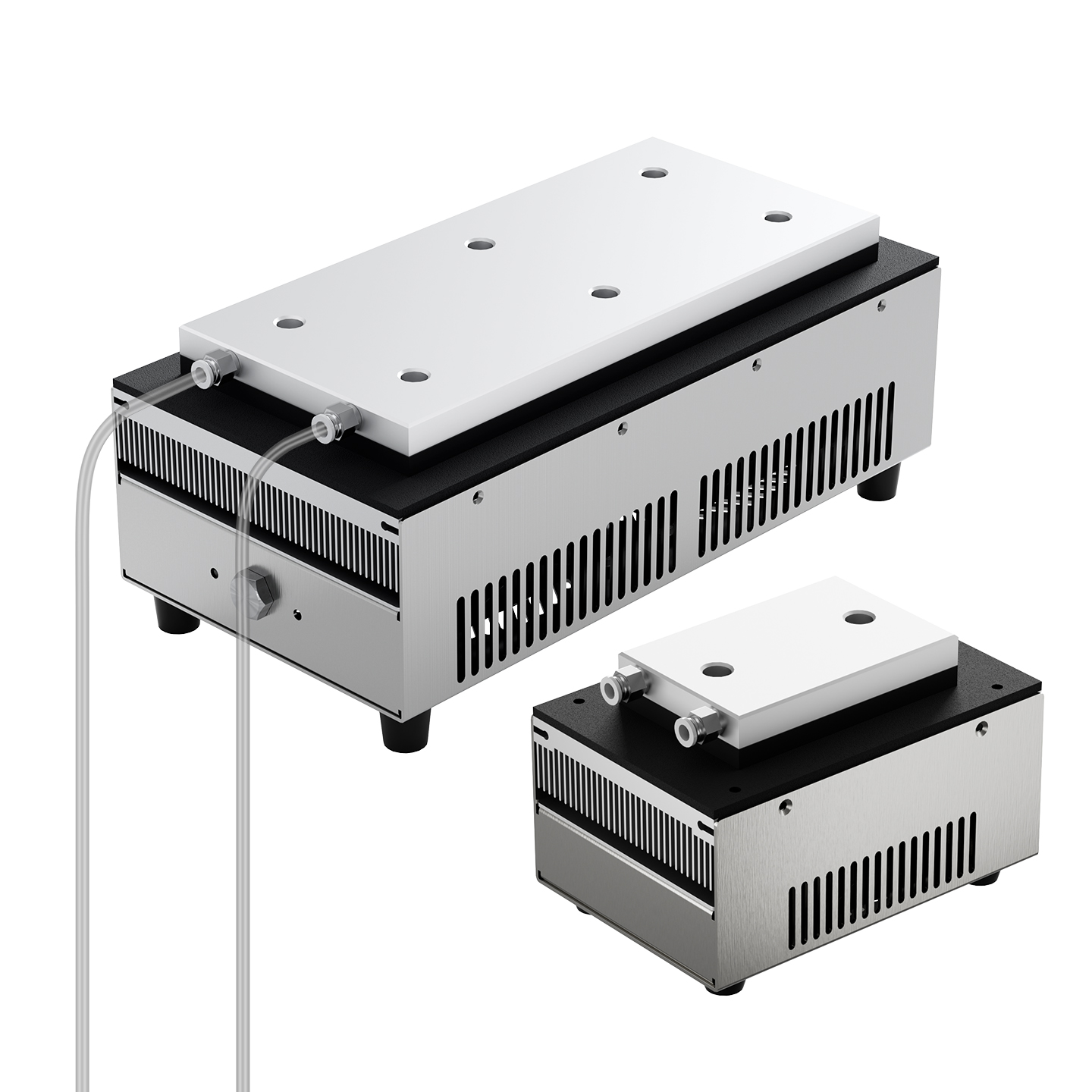
Peltier liquid cooling module
HETL is the liquid-to-air thermoelectric module family for liquid-related temperature control. It uses the HET series heat-sink and cooling-capacity coding system. Confirm the liquid circuit, heat-rejection arrangement and pump requirements for the selected assembly.
- Model family
- HETL
- Technology
- Peltier thermoelectric cooling
- Configuration
- Liquid cooling circuit
View technical specifications ↓
Send your operating conditions and quantity for model selection, specifications and a quotation.
ENGINEERING DATA / HETL
Specifications & selection.
Product overview
HETL is the liquid-to-air thermoelectric module family for liquid-related temperature control. It uses the HET series heat-sink and cooling-capacity coding system. Confirm the liquid circuit, heat-rejection arrangement and pump requirements for the selected assembly.
- Solid-state Peltier cooling without a compressor or refrigerant.
- Cooling and heating through controlled reversal of TEC current, using a compatible controller.
- TEC1-127xx elements are the standard platform; TEC2, TES1 and TEC1-199 options are listed in the source catalogue.
- Heat-sink, capacity and voltage combinations can be discussed for custom assemblies.
Technical specifications
| Parameter | Published specification |
|---|---|
| Published family capacity catalogue | 53–1064 W; 32 combinations of 8 base capacities and 4 element counts |
| Supply platforms | 12 / 24 / 48 VDC; depends on the selected assembly |
| TEC array limit | Up to 4 in series × 4 in parallel; 16 elements maximum |
| Element counts | 1 / 2 / 4 / 8 / 16 |
| Single-element maximum temperature difference | ≥66 °C; TEC2-19010 two-stage option: ≥80 °C |
| Heating / cooling | Bidirectional with a suitable reversing controller |
| Standard heat-sink codes | 101 / 102 / 151 / 152 / 153 / 154 / 156 |
| Source test condition | 25 °C ambient unless otherwise stated |
| Complete-unit dimensions and weight | Not specified in the source tables; obtain the selected model drawing |
Capacity values are the published series catalogue ratings, not electrical input power or a guaranteed cooling result at every operating condition. The single-element temperature difference is not the cabinet or liquid temperature reduction. Select against heat load, ambient temperature and the model performance data.
Model selection
These are the standard model combinations listed on the Chinese product page. Other heat-sink, capacity and voltage combinations require model-specific confirmation.
| Model | Heat sink W × L (mm) | Cooling capacity (W) | Supply (VDC) |
|---|---|---|---|
| HETL-101-075 | 100 × 150 | 75 | 12 |
| HETL-151-106 | 150 × 200 | 106 | 24 |
| HETL-102-150 | 100 × 215 | 150 | 24 |
| HETL-152-212 | 150 × 300 | 212 | 48 |
| HETL-153-300 | 150 × 400 | 300 | 48 |
| HETL-154-424 | 300 × 300 | 424 | 48 |
| HETL-156-600 | 300 × 400 | 600 | 48 |
Dimensions in this table refer to the hot-side heat-exchange surface, not the overall enclosure or the cabinet cutout. Earlier model names omit the voltage suffix; use the corresponding technical specification to confirm supply voltage.
How to read the model code
HETL – [heat-sink code] – [capacity W] – [voltage]
Published example: HETL-153-300-48V
| Field | Meaning |
|---|---|
| Series | HETL — liquid to air |
| Heat-sink code | 101, 102, 151, 152, 153, 154 or 156 |
| Capacity code | 053 to 1064, in W; leading zero retained for values below 100 |
| Voltage suffix | 12V / 24V / 48V |
Module families HETD and HETL do not use an installation-code field.
Heat-sink dimensions
| Code | Width (mm) | Length (mm) | Construction |
|---|---|---|---|
| 101 | 100 | 150 | Single heat sink |
| 102 | 100 | 215 | Single heat sink |
| 151 | 150 | 200 | Single heat sink |
| 152 | 150 | 300 | Single heat sink |
| 153 | 150 | 400 | Single heat sink |
| 154 | 300 | 300 | Two 152 heat sinks side by side |
| 156 | 300 | 400 | Two 153 heat sinks side by side |
Codes 154 and 156 use double-width assemblies. Code 155 is not listed. Complete assembly dimensions, weight and mounting cutouts must be checked against the selected model drawing.
Cooling-capacity catalogue
| 1 element | 2 elements | 4 elements | 8 elements |
|---|---|---|---|
| 053 | 106 | 212 | 424 |
| 062 | 124 | 248 | 496 |
| 075 | 150 | 300 | 600 |
| 080 | 160 | 320 | 640 |
| 088 | 176 | 352 | 704 |
| 097 | 194 | 388 | 776 |
| 106 | 212 | 424 | 848 |
| 133 | 266 | 532 | 1064 |
The source defines 32 combinations, including repeated wattage values. Its 1064 W upper catalogue value uses eight TEC1-12715 elements. The array limit of 16 elements is a separate configuration limit, not an additional published capacity row.
Supply and TEC configuration
| Suffix | Source configuration |
|---|---|
| 12V | One 12 V-class element, or 2 / 4 elements in parallel |
| 24V | Two 12 V-class elements in series; alternatively a single or parallel 24 V-class TES1-24106 / TEC1-19911 arrangement |
| 48V | Four 12 V-class elements in series; 4-series × 2-parallel (8 elements) or 4-series × 4-parallel (16 elements) |
Match the assembly nameplate voltage and polarity. Do not mix different TEC element models within one assembly.
Compatible temperature controllers
| Controller | Output / interface | Source selection guidance | Listed control accuracy |
|---|---|---|---|
| ETC80-RB | Relay output / dry contact | Below 24 V AND below 10 A | ±0.5 °C |
| ETC80-HB | H-bridge MOSFET; PWM; reverse heating; RS485 | 212 W and above | ±0.1 °C |
For the 150–212 W transition range, check both voltage and current. The source recommends ETC80-HB at 212 W and above. These are controller accuracy figures; achieved system temperature uniformity and stability also depend on the sensor, load and installation.
Installation and operation
- Maintain liquid circulation, bleed air from the circuit and start the pump before powering the thermoelectric assembly.
- Confirm the pump, coolant and flow requirements for the selected assembly; the source does not state a universal flow-rate value.
- Manage condensation and prevent liquid from reaching electrical components.
- Stop power immediately if required heat rejection fails, including fan failure or loss of liquid circulation. Continued operation can permanently damage the TEC elements.
- Use the nameplate supply and the correct polarity. Heating mode also requires normal heat rejection.
- Clean air-cooled heat-sink fins and filters regularly; service coolant on liquid-circuit assemblies.
- Disconnect power and store dry when unused for long periods.
The source identifies HETL as “Liquid to Air”, but its overview also describes hot-side liquid cooling. Confirm the actual liquid-side arrangement on the model drawing before integration.
Translated from the official Chinese product details ↗, checked 14 September 2026. Downloaded PDF editions retain their printed revision dates; confirm the applicable specification when ordering.
TECHNICAL RESOURCES
Plan your integration.
English technical specification · YZ26A06
Confirm the exact variant, supply voltage, dimensions and operating conditions with our team before ordering.
Official product reference (Chinese) ↗SELECT YOUR COOLING APPROACH